Draw Circle Using Rectf Android
Did you ever want to create highly-customized user interfaces in Android? And so this is the tutorial for you!
To depict custom shapes, you need to keep iterating until you achieve the beautiful art you want. In this tutorial, you'll learn how to draw your blueprint on paper first to avert wasting time via trial and error.
You'll improve an app called Stars of Science. Yous'll acquire how to create custom shapes past painting a contour card with a curved custom shape and slope colors.
Throughout the tutorial, you lot'll acquire how to:
- Prepare a custom shape on newspaper earlier coding.
- Extend the Android
Viewto draw and pigment it on theCanvas. - Draw a curved shape in gradient colors.
The custom shape y'all'll create will await like this:

Notation: This tutorial assumes yous understand the basics of Android evolution with Kotlin. If you're new to Android evolution, please become through Outset Android Development with Kotlin to understand the basics. If y'all're new to Kotlin, check out this Introduction to Kotlin tutorial.
Getting Started
Download the projection materials by clicking the Download Materials button at the top or lesser of this tutorial. Launch Android Studio three.half dozen.1 or afterward and select Open an existing Android Studio project. Then navigate to and select the starter project folder where you'll detect the files you demand to first, forth with some widgets.
Your app already has its basic UI set up then y'all tin can focus on drawing custom shapes in Android.
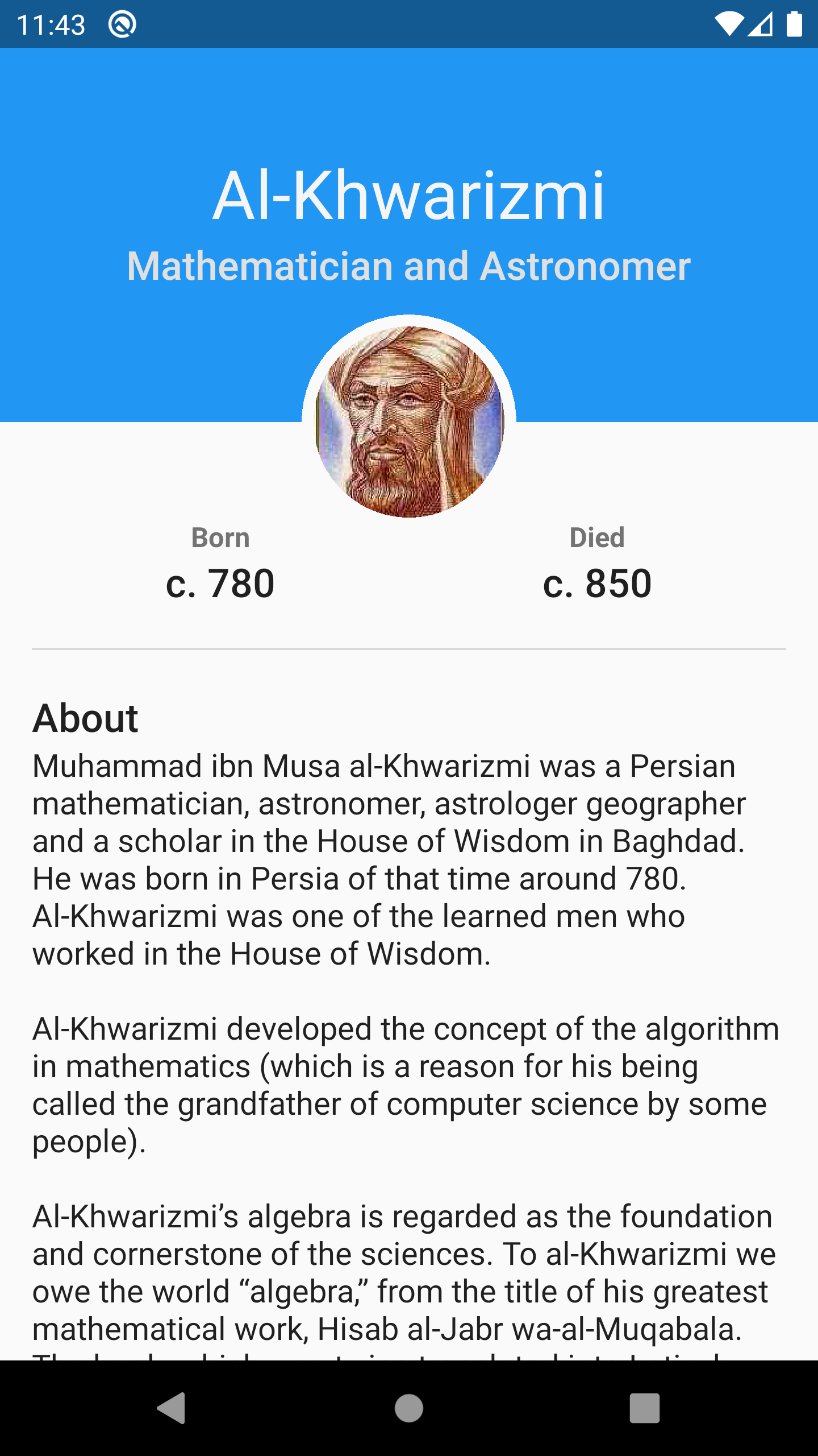
Build and run the app. You'll see the post-obit screen on your mobile telephone or Android emulator:

It's great, merely the top of the bill of fare doesn't have much pizazz. Y'all'll change that throughout the tutorial.
Exploring the Project
Take a quick look at the project structure. Aggrandize starsofscience package and check out the folders inside:

Here's a breakdown of the folders:
- utils contains four files with extension functions you'll utilize in your painting journey.
- view contains
CircularImageViewwhich you'll use to display the avatar in a circular shape. The code within this grade is out of the scope of this tutorial. - starsofscience contains three files:
- MainActivity.kt is the app's principal and luncher activity.
- Painter.kt contains paint() which you'll implement to pigment your custom shape. You'll add all drawing and painting logic to this function.
- CustomPainter.kt is a custom Android View with a constructor accepting the width and height of your custom shape in addition to a painter object that has all the drawing and painting logic. This
CustomPainteroverridesonDraw()and delegates all the cartoon to the painter by executingcanvas?.let(painter::pigment).
Now that you know more nearly the classes y'all'll piece of work with take a moment to learn some of the theory behind making cute shapes.
Coding Your Shapes
Before diving into drawing with Android Canvas, you need to know which tools you'll need, how to use them and how to ready to code your target shape.
Think virtually drawing in the physical world. To describe a shape, yous demand to get a pencil and paper and and then use your hand to move the pencil beyond the paper's surface. Finally, if y'all want to arrive beautiful, you demand to get a brush with some paint.
In this section, you'll starting time by drawing a shape freehand. Catch a pencil and paper and get gear up!
Know Your Canvas
Your sheet acts equally the digital version of the slice of paper y'all draw on. It holds all your drawing elements, including lines, curves, arches, shapes, text and images.
The canvas needs a size, including width and top. Drawing on a canvas without knowing its size can atomic number 82 to unexpected results.
On your paper, earlier drawing any shape, define the canvas by drawing a rectangle of whatsoever size you want. Any shapes you draw afterward will exist relative to that sheet.

Note: Y'all don't want your shapes to have an absolute position or size. Instead, make them relative to the size of the canvas. This lets you display your shapes on different devices with dissimilar screen sizes.
For case, yous might place your shape at the center of the canvas or make its size equal to one-half of the canvas size.
Now that yous have a canvas, information technology's time to create a shape.
Defining How to Move Your Pencil
In visual arts, you have to move your pencil properly across the newspaper's surface to create your artwork. Yous'll use the aforementioned mechanism to depict on the canvas.
Before you can draw a shape, you need to consider which functionalities the canvas object needs to have.
For example, if yous want to draw a square, you need to draw four lines. So, you need the drawing line function in your framework. On the other mitt, if you desire to draw a crescent, you need to describe two curves with the cartoon curve office.
Pick upward your pencil and draw a circle in the center of the circle that'due south a quarter of the width, like this:

Now, to convert that shape on your newspaper into a shape in Android, you need to consider its coordinates.
Computing Coordinates
Coordinates are pairs of numbers that define the exact location of a signal on a plane.
Before you draw anything, you need to know the main points that make upwards that shape. For good practice, calculate all the coordinates and dimensions on your newspaper earlier writing any code. This saves you coding time and makes you focus on translating that shape from the paper onto your device.
Since you already drew a circle relative to the canvas on your paper, you lot already calculated two things:
- The center of the circle: Since your circumvolve is at the center of the canvas, the centre of the circle is the center of the canvas. So the x coordinate of the circle'due south center is equal to half of the width of the canvas and the y coordinate of the circle'south heart is equal to half of the elevation of the canvas. This means that:
cx = canvas width / 2
cy = canvass elevation / 2 - The radius: Since your circle is a quarter of the canvas width, the diameter of the circumvolve is equal to a quarter of the width of the canvas. The radius is equal to half of the bore. That ways:
diameter = sheet width / 4
radius = bore / 2 = canvas width / 8

Meet, drawing your shapes on newspaper helps you calculate the points you need to draw your shape relative to the canvass.
Information technology's efficient to visualize what you demand to do before it'due south fourth dimension to translate your ideas into code. Making paper sketches is a prerequisite for your custom drawing! :]
Using CustomPainter
At present that you lot've learned some theory, it's time to start using the Android Sail and add some code that volition reproduce your cartoon in the app.
Implementing the Painter Interface
Beginning by creating a new class ProfileCardPainter in the starsofscience package. Then replace the whole file content with:
packet com.raywenderlich.android.starsofscience import android.graphics.* import androidx.annotation.ColorInt //1 class ProfileCardPainter( //2 @ColorInt individual val colour: Int ) : Painter { //iii override fun paint(sail: Canvas) { } } Here you:
- Define a new grade named
ProfileCardPainterthat implements the interfacePainter. - And so in its primary constructor y'all ascertain the profile color as a course holding.
- Finally, yous implement
pigment(canvas: Sheet).CustomPainterwill phone call this method whenever the object needs to pigment.You'll write all your cartoon code inside this function, which gives you 1 parameter: The
canvasto draw on.
Rendering With CustomPainter
Go to MainActivity.kt. You lot'll find the following line of code in onCreate():
profileCardContainer.setBackgroundColor(R.color.colorPrimary.toColorInt(this)) Information technology sets a groundwork color to the profileCardContainer which is a FrameLayout already defined in XML. You lot don't need that line anymore because you want to add together your custom shape instead of that solid color.
Supervene upon that line with the following code:
//1 val azureColor = R.color.colorPrimary.toColorInt(this) val avatarRadius = R.dimen.avatar_radius.resToPx(this) val avatarMargin = R.dimen.avatar_margin.resToPx(this) val cardWidth = ViewGroup.LayoutParams.MATCH_PARENT val cardHeight = R.dimen.profile_card_height.resToPx(this).toInt() //ii val painter = ProfileCardPainter( colour = azureColor ) //3 profileCardContainer.addView( CustomPainter( context = this, width = cardWidth, pinnacle = cardHeight, painter = painter ) ) Add whatsoever missing import by pressing Option+Enter on Mac or Alt+Enter on PC.
In the code above:
- You define the backdrop of your custom shape: Color, avatar radius, avatar margin, width and height.
- Then, you create a
ProfileCardPainterwith the color you previously defined. - Finally, you add a new
CustomPainterequally a subview ofprofileCardContainerpast passing all its needed properties:-
contextto create this custom AndroidView. -
widthandheightof the custom shape. -
painterresponsible for all the drawing logic.
-
Build and run the app to see… a pretty ugly menu because you haven't drawn anything nevertheless. Don't worry, you'll showtime drawing something in a moment. :]

Drawing Your Offset Shape
In this section, you'll practice with the tools you demand to draw in the computer graphics world. They're a lot like the physical tools yous used to draw a circle on a paper. Then, with this knowledge, you'll depict your first shape!
Note: Graphics libraries have similar APIs for drawing, which makes drawing in Android comparable to drawing in iOS, Flutter and the web. When you main cartoon custom shapes on ane platform, information technology'south piece of cake to reuse this knowledge on other platforms.
Drawing and Painting a Rectangle
To draw a rectangle, yous need to create a RectF object with the size y'all want. You then need a Paint object with the colour you prefer to beginning drawing that RectF on the canvass.
RectF is a uncomplicated class with four immutable bladder properties: Left, top, right and bottom. These four numbers represent a rectangle, where:
- Left is the left-most point on the x-axis.
- Top is the superlative-nigh signal on the y-axis.
- Right is the right-most bespeak on the x-axis.
- Bottom is the lesser-most signal on the y-axis.
Note: You lot can calculate whatsoever extra properties in RectF, like the width and height, based on these four main properties.
In this tutorial, you'll rely on RectF for your shape bounds. Yous'll draw each shape inside of and based on a certain RectF.
In ProfileCardPainter.kt, go to paint() and add the following:
//1 val width = canvas.width.toFloat() val height = sheet.peak.toFloat() //2 val shapeBounds = RectFFactory.fromLTWH(0f, 0f, width, summit) //3 val paint = Pigment() paint.color = color //4 sail.drawRect(shapeBounds, paint) Add together any missing import by pressing Option+Enter on Mac or Alt+Enter on PC.
Hither's what this code defines:
- The
widthandheightof the canvas. -
shapeBoundsis aRectFwith a size that fits the whole area of the canvas by using the factory functionfromLTWH(). -
paintis your paint and its color. - Finally, you depict your
shapeBoundson thesailby passing it todrawRect()along with yourpaintfrom the previous line.
At present, build and run the app. See that the menu now has a blue rectangle as its groundwork. Hooray, y'all've drawn your first shape! :]
That's better, but there'southward still much room for improvement!
Using a Path to Draw the Profile Card
A path is not a bitmap or raster, and it doesn't have pixels. Information technology's an outline that represents a series of smooth lines, arcs or Bézier curves. Using a path makes your shapes scalable and independent of the screen's resolution.
Path is a powerful class that you can use in many situations. For example, you tin clip a bitmap by a path, or you lot can use a path to draw a custom shape like you're about to do right now.
Drawing the Contour Card
In this section, you'll start using the Path grade to describe a more complex shape like the blue shape here:

But before y'all kickoff, you need to do some preparation.
In that location are a few things y'all should note in the previous image:
- Black dashed rectangle: Represents the whole canvas.
- Cherry-red dashed rectangle: Marks the bounds of the bluish shape. It has the same width and superlative equally the canvas, except that yous subtract the avatar radius from its acme.
- Bluish shape: A rectangle with a half circle, an arc of a circle, as a negative space at the bottom eye. This arc should take a radius equal to the radius of the avatar.
Notation: An arc is a segment of a curve. In this case, the arc you lot'll use is a section of a circle's circumference, besides called a circular arc.
The image below shows a blue arc that starts at the aught degree angle and sweeps to 90 degrees.

First, get the radius of the avatar. Start by calculation a new class property chosen avatarRadius to your ProfileCardPainter main constructor:
class ProfileCardPainter( @ColorInt individual val color: Int, individual val avatarRadius: Float ) : Painter { So, go to MainActivity.kt and, in onCreate(), pass the avatarRadius to ProfileCardPainter:
val painter = ProfileCardPainter( color = azureColor, avatarRadius = avatarRadius ) Finally, return to ProfileCardPainter.kt and update the shapeBounds by subtracting the avatarRadius from its height in fromLTWH():
val shapeBounds = RectFFactory.fromLTWH(0f, 0f, width, height - avatarRadius) 
To see the results build and run the app:

Neat! Now the blue background stops halfway downwards the length of the avatar.
Adding Negative Space Around the Avatar
Side by side, you'll add some negative space to the blue shape to set up it apart from the avatar. Add a new function called drawBackground() to ProfileCardPainter:
individual fun drawBackground(canvas: Canvas, bounds: RectF, avatarBounds: RectF) { //ane val pigment = Paint() paint.color = color //2 val backgroundPath = Path().employ { // 3 moveTo(premises.left, bounds.acme) // 4 lineTo(bounds.bottomLeft.x, bounds.bottomLeft.y) // 5 lineTo(avatarBounds.centerLeft.x, avatarBounds.centerLeft.y) // 6 arcTo(avatarBounds, -180f, 180f, faux) // seven lineTo(bounds.bottomRight.ten, bounds.bottomRight.y) // 8 lineTo(premises.topRight.x, bounds.topRight.y) // ix shut() } //ten canvas.drawPath(backgroundPath, paint); } Add any missing import by pressing Choice+Enter on Mac or Alt+Enter on PC. To import all the extension functions you need for RectF in a row, add the following import:
import com.raywenderlich.android.starsofscience.utils.* This diagram illustrates the proper coordinates for each point you need to build the path.

In the previous code:
- You create a
Paintobject and gear up its color. - Then, you create a
Pathobject. - You move to the acme-left corner, P1, without drawing a line. This is similar moving a pencil to a starting point without touching the paper.
- Next, you add together a straight line that starts at P1 and ends at P2.
- Then, you add a directly line that starts at P2 and ends at P3: The indicate at the border of where you will start drawing the arc.
- Then, starting from P3, add together an arc in the upper half region of the avatar bounds: The arc starts from the bending
-180degrees and sweeps by180degrees catastrophe at P4.
You lot passfalseas the last parameter to prevent starting a new sub-path for the arc. This tells Android that yous want the arc on the same path. - Adjacent, you add a straight line that starts from the current bespeak and ends at P5 at the bottom-right corner.
- You terminate by calculation a straight line that starts from the electric current point P5 and ends at the given point P6 at the top-right corner.
- Then you shut the path by adding a straight line that starts at the current indicate P6 and ends at the beginning point on the path, P1.
- Finally, you draw the
backgroundPathon the canvas by passing it todrawPath()withpaint.
In the previous code, you lot can plummet lines v and six in a single line. Do you know how? You can find the solution in the spoiler below.
[spoiler title="Solution"]
Y'all tin collapse lines v and half-dozen by leaving only line six.
arcTo(avatarBounds, -180f, 180f, false) The official documentation of
arcTo(RectF oval, float startAngle, float sweepAngle, boolean forceMoveTo)
states: "If the start of the path is different from the path'southward electric current last bespeak, and so an automatic lineTo() is added to connect the current contour to the start of the arc."
[/spoiler]
Phew! That was a lot of code, but information technology was worth the effort!
Creating the Rectangle Around the Avatar
In ProfileCardPainter, get to paint() and replace the last iii lines:
val paint = Paint() paint.color = color sheet.drawRect(shapeBounds, pigment) with the following lawmaking to create a new RectF effectually the avatar:
//1 val centerAvatar = PointF(shapeBounds.centerX(), shapeBounds.lesser) //2 val avatarBounds = RectFFactory.fromCircle(middle = centerAvatar, radius = avatarRadius) //3 drawBackground(sheet, shapeBounds, avatarBounds) Here'southward what this code does:
- You create a
PointFobject for the center point of the avatar, wheretenis theshapeBounds.centerX()andyis thelesserof theshapeBounds. - Then, you create a
RectFobject from the avatar circle usingfromCircle(). The center iscenterAvatar, which you just created, and the radius is theavatarRadius. - Finally, you call
drawBackground()and pass the canvas with rest of the parameters to draw your beginning path.
Build and run the app. You'll come across this:
You lot probably don't detect the deviation yet. Don't worry, yous'll set up that next.
Adding a Margin Around the Avatar
There is a departure, but you can't see it because the negative space is exactly equal to the circular avatar's size. Side by side, you lot'll make that negative space a bit bigger to leave a margin between information technology and the avatar.
First, get the margin of the avatar. Kickoff past adding one more class property called avatarMargin to your ProfileCardPainter principal constructor, don't forget the comma at the finish of the line higher up the new code.
form ProfileCardPainter( ... private val avatarMargin: Float ) Then, get to MainActivity.kt and, in onCreate(), pass the avatarMargin to the ProfileCardPainter constructor:
val painter = ProfileCardPainter( ... avatarMargin = avatarMargin ) Finally, render to ProfileCardPainter.kt and\where you create the avatarBounds in paint , add together .inflate(avatarMargin) to the finish:
val avatarBounds = RectFFactory.fromCircle(heart = centerAvatar, radius = avatarRadius).inflate(avatarMargin) Calling inflate() on a RectF creates a new RectF object whose left, meridian, right and bottom edges are moved outwards by the given value. The result is a nice space around the avatar.
To encounter the margin in activeness, build and run the app.
Pretty... only ordinary. Next, you'll spice up the background by calculation an bonny curved shape.
Calculation More Smashing Shapes
To enhance your custom shape, y'all tin add some simple decorations similar stars or circles in a partially-faded color. For this app, you'll add a more interesting ornamentation: A curvy shape in slope colors.
Adding a Curved Shape
Before you lot starting time drawing, take a moment to learn about the different types of curves. The Quadratic Bézier Bend and the Cubic Bézier Curve are two ordinarily used curves.
- A quadratic Bézier curve requires three points to describe: A start point, an endpoint and a handle betoken that pulls the curve towards information technology.

- A cubic Bézier curve needs four points to describe: A commencement bespeak, an end point and two handle points that pull the bend towards them.

Next, you'll utilize a quadratic Bézier curve to create an interesting groundwork shape.
Drawing a Quadratic Bézier Curve
Start past creating a new function chosen drawCurvedShape() within ProfileCardPainter with the post-obit:
individual fun drawCurvedShape(canvas: Canvas, premises: RectF, avatarBounds: RectF) { //i val paint = Paint() paint.color = color.darkerShade() //2 val handlePoint = PointF(bounds.left + (bounds.width() * 0.25f), premises.top) //3 val curvePath = Path().apply { //4 moveTo(bounds.bottomLeft.ten, bounds.bottomLeft.y) //5 lineTo(avatarBounds.centerLeft.x, avatarBounds.centerLeft.y) //6 arcTo(avatarBounds, -180f, 180f, false) //vii lineTo(premises.bottomRight.x, bounds.bottomRight.y) //8 lineTo(premises.topRight.x, bounds.topRight.y) //9 quadTo(handlePoint.10, handlePoint.y, premises.bottomLeft.ten, bounds.bottomLeft.y) //10 close() } //eleven canvas.drawPath(curvePath, paint) } This diagram will aid you lot understand the code you added. Apply it as a guide to the proper coordinates for each point you'll build to create the path:

In the previous code:
- You create a
Pigmentobject and set its color to a darker shade of the profile colour. - Then, you create a handle point at the summit left corner of the
RectF, shifted to the right past 25% of the width of theRectF. This is P6 in the guide image. - You create a
Pathobject. - Then, you movement to the lesser-left corner, P1 in the guide epitome.
- You add together a straight line that starts from P1 and ends at P2: The middle indicate at the border of the black dashed avatar premises
RectF. - And so, starting from the current point, P2, add together an arc in the upper- half region of the avatar bounds: The arc starts from the angle
-180degrees and sweeps past180degrees ending in P3.
Y'all passsimulatedequally the last parameter and so you don't kickoff a new sub-path for the arc. This tells Android that you want the arc on the same path. - Y'all add a straight line that starts from the current point and ends at the given bespeak, the bottom-correct corner. This adds a line from P3 to P4.
- Then, you add a direct line that starts from the electric current indicate and ends at the given point, the tiptop-correct corner, adding a line from P4 to P5.
- You add a quadratic Bézier curve that starts from the electric current point, P5, and ends at the bottom-left corner, P1, using the handle point you created in step ii.
- Finally, you close the path, even though information technology'south not required this time since you are dorsum at the offset bespeak on the path.
- You draw
curvePathon the canvas past passing it todrawPath()along with thepaintobject.
Finalizing the Curve
You're near finished creating the curve. In ProfileCardPainter, go to the last line in paint() and add together the post-obit code:
//ane val curvedShapeBounds = RectFFactory.fromLTRB( shapeBounds.left, shapeBounds.top + shapeBounds.acme() * 0.35f, shapeBounds.right, shapeBounds.bottom ) //2 drawCurvedShape(canvass, curvedShapeBounds, avatarBounds) Here, you lot:
- Create a
RectFthat is similar to theshapeBoundsrect, except you lot've shifted its top slightly to the bottom by 35% of theshapeBounds' tiptop: This is the ruby-red dashedRectFin the paradigm above. - Call
drawCurvedShape()and pass thesheetobject, the curved shape premises and the avatar bounds to it.
Build and run the app to run across the slap-up background bend behind the avatar:

And then you're done, correct? Almost. There'south yet 1 more than finishing touch y'all need to add.
Calculation Gradient Paint
You've created your offset beautiful, custom curved shape, simply your graphic designer wants you to do 1 more thing: Add gradient colors to your curved shape.
At that place are different types of shaders or gradients, including linear gradients, which transition through at least two colors in a straight line, and radial gradients, which transition through colors starting from a central point and radiating outward.
Correct now, y'all'll create a shader, a linear slope described by three colors. Each colour needs a stop to specify its position on a line from 0.0 to 1.0.
Start by creating a new function called createGradient() within ProfileCardPainter with the following code:
private fun createGradient(bounds: RectF): LinearGradient { //ane val colors = intArrayOf(color.darkerShade(), color, color.darkerShade()) //2 val stops = floatArrayOf(0.0f, 0.3f, 1.0f) //3 return LinearGradient( premises.centerLeft.x, bounds.centerLeft.y, bounds.centerRight.x, bounds.centerRight.y, colors, stops, Shader.TileMode.REPEAT ) } Here's what'south going on in this lawmaking:
- You create a list of three colors, where the middle color is the profile color and the kickoff and last colors are darker shades of that profile color.
- Then you create a list of three stops. The start is 0.0, which puts the corresponding color in the colors list at the zippo position of the gradient color. In the same way, the middle and the stops specify the positions of their corresponding colors in the color list.
- Finally, you lot create a linear slope past passing the start coordinates and the end coordinates of the slope with the given colors and stops, and the shader TileMode to repeat the gradient in instance the area which you fill is larger than the shader yous created.
Now get to drawCurvedShape() and update the paint object to use the new linear gradient instead of a solid color.
Supersede this line:
pigment.color = color.darkerShade() With this 1:
paint.shader = createGradient(premises) Here, you create a new gradient and ready it to the paint object.
Finally, build and run the app to see a gradient within the groundwork curve:
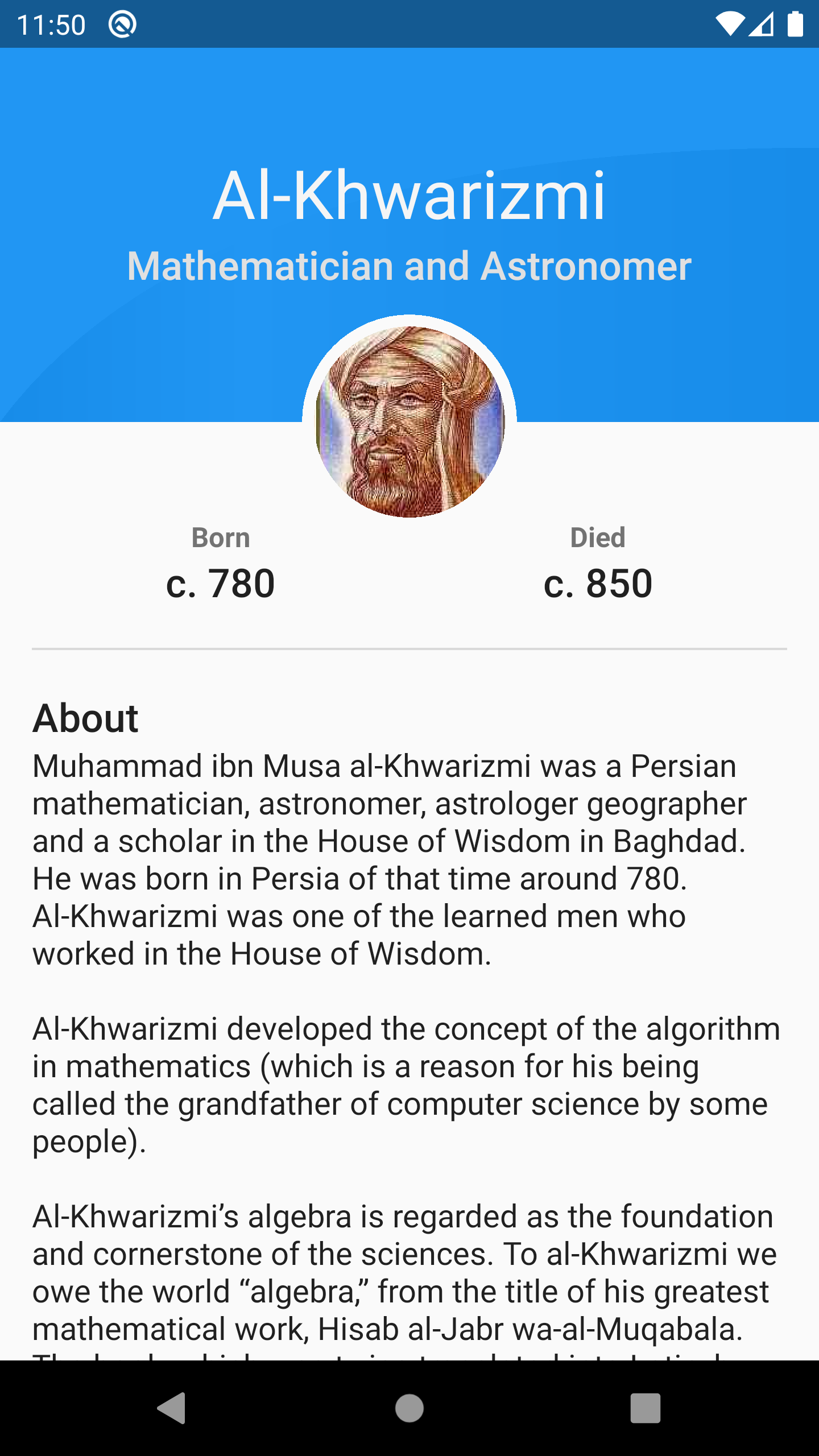
Congratulations! You've created a cute contour card with an eye-catching custom groundwork shape and shading.
Where to Go From Here?
You lot tin can download the completed concluding projection using the Download Materials push button at the top or bottom of the tutorial.
Wow, that was a lot of work! But you learned a lot, too. In add-on to taking a deep look at Sheet and many Android Graphics APIs, you learned how to:
- Prepare your custom shape on newspaper before coding.
- Apply
Pathand how to add different lines to it sequentially. - Draw a curved shape in slope colors.
To learn more about Canvas and Android custom views check out the post-obit links:
- Android Custom View Tutorial.
- Making your drawing Interactive.
- Custom Android Compound View.
Besides, you can check RichPath library. It's an open-source library that gives you full control over your custom shapes in vector drawable format so you can manipulate and breathing them hands at runtime.
Experience gratuitous to share your feedback, comments or ask questions in the forum below. Don't stop drawing. ;]
munizwourfact1993.blogspot.com
Source: https://www.raywenderlich.com/9556022-drawing-custom-shapes-in-android
0 Response to "Draw Circle Using Rectf Android"
Post a Comment